How to Use & Read a Multimeter Safely
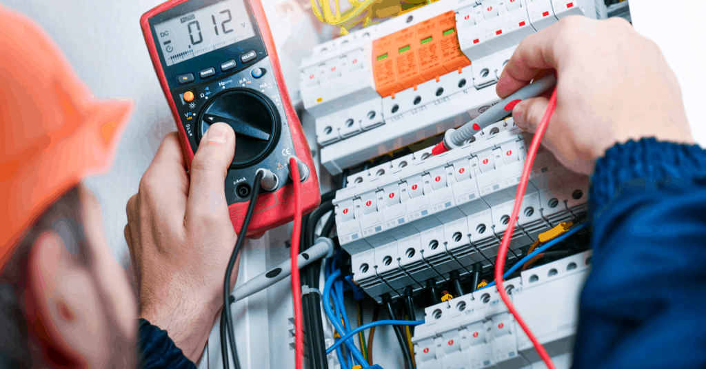
For electricians and technicians, a multimeter is a must-have device since most electrical equipment can't be fixed without one. Whether it's for complex or straightforward devices or circuits, a multimeter is an essential tool for measurement. But, to check any sort of fault in an electrical device, a person must know how to safely use and read a multimeter.
To help out beginner electricians, we're going to discuss a step-by-step guide on using a multimeter for different electrical parameters, such as voltage, resistance, and so on.
What is a Multimeter & Why Should We Use It?
A multimeter is a measuring instrument used to measure different electrical properties, such as voltage, resistance, current, and continuity. Some of the multimeters also offer diode testing and temperature measurement.
There are two main types of multimeters available on the market today; a digital multimeter and an analog meter. The readings on analog meters are represented by a deflection of a needle scale, while digital meters use a digital display to provide readings or measurement values.
With a multimeter, you can speed up your troubleshooting process of electrical equipment. For example, if you need to check electrical wiring for damage, all you need to do is run a continuity test. (We'll tell you how to use a multimeter for continuity in this article)
Parts of a Multimeter

Before we discuss instructions on using a multimeter, you must understand the anatomy of its various parts and how to use all aspects of it to measure and read measured results.
Display Panel – It displays measured results to the user.
Selection Knob – It is used to select the electrical property you want to measure, as well as its range. The selection knob can be used to set voltage, resistance, and current, etc. More modern multimeters still have the mode selection knob but use auto-ranging to select the correct range of the setting.
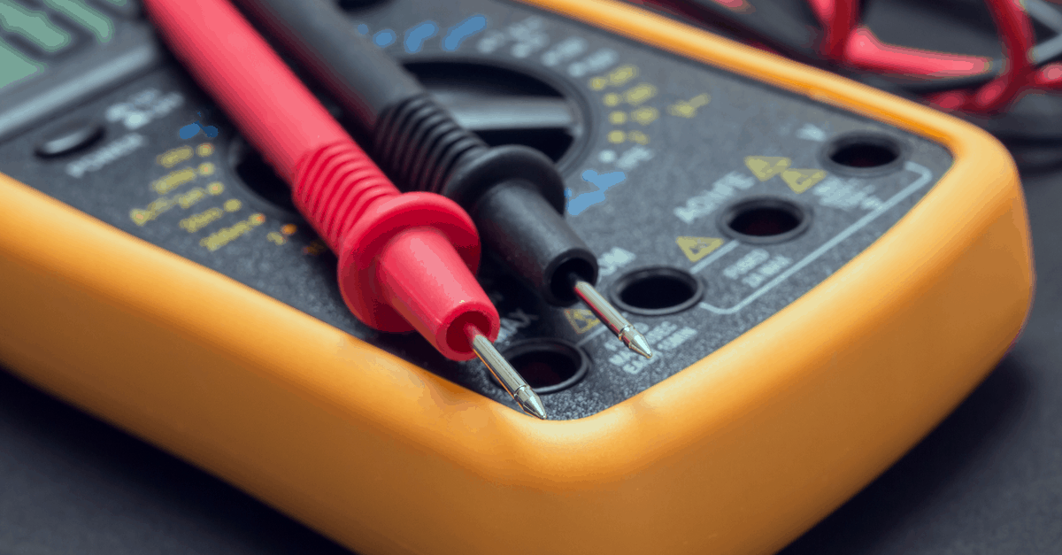
Ports – Most multimeters have three different ports; a 10A port, a COM port, and a mAVΩ port. COM port is Common. Usually, technicians connect one end of a black probe with a COM port and the other end with a negative or Common of circuit. The mAVΩ port is used to measure current (up to 200mA in some meters), voltage, resistance, and continuity. Usually, technicians connect a red probe (Positive) into this port. For currents greater than 200mA, the 10A port is used instead of the mAVΩ port in some meters.
Now that you're well aware of multimeter parts and how to use them. It's time to jump to instructions on how to use a multimeter for successful measurements.
How to Measure & Read Voltage with a Multimeter?
To use a multimeter to test voltage between two points in a circuit, follow these simple steps.
- Before even considering testing something, make sure all your equipment is in good condition and that there is no damage to the leads. A damaged lead can expose the user to dangerous voltages.
- Plug in the black probe (Negative or ground probe) into the COM port of a multimeter.
- Plug in the red probe (Positive) into the mAVΩ port.
- Use the selection Knob to select DC or AC voltages. You can also set your range for more accurate measurements. If you're going to measure voltage in a circuit where voltages are not high, set a low range. For example, for voltages up to 15V or 16V, select a range of 20V.
- Some of the meters have auto-ranging features. If you're using an auto-ranging meter, then just select DC or AC Voltage using the selection knob.
- Connect the tip of the red probe with a second point. Both probes must be connected in parallel with the points where you want to measure voltage.
- Keep in mind that AC voltage does not have polarity.
- Now, you will be able to see voltage reading on display.
Note: If a circuit max voltage is unknown, then set a maximum voltage range.
How to Use a Multimeter for Current Measurement

To use a multimeter to test current passing through, follow these simple steps. Ensure the circuit you are testing is known to be a low-current circuit, below the maximum current rating for the meter. Measuring current over the specified limit is dangerous and may cause the multimeter to blow its fuse. If you do not know the current being measured, or suspect it will overload the meter, use a clamp meter instead.
- Unplug the circuit to turn it off completely to ensure protection.
- Insert the Black probe into the COM port.
- Insert Red probe into the 10A Port. In some meters, you may find a 20A port instead of a 10A port. Some meters don't have another port for current measurement, so one can measure current using the same port as voltage. There are also some meters available in which you can measure current up to 200mA using mVAΩ. So, check your meter before taking this step.
- Now connect both tips of the probe in a circuit using the parallel connection. You have to break a circuit to connect your meter probes in a parallel way.
- Select maximum range of current using the selection knob. If your meter is auto-ranging, then you don't have to worry about the range.
- Turn on the circuit, and read measured values on the display panel of a multimeter.
For measuring current without breaking a circuit, you can use a clamp meter.
How to Measure & Read Resistance with a Multimeter?
To use a multimeter to find resistance of a component, follow these simple steps:
- If you want to know the resistance of an attached component or a part of the circuit, then turn off the circuit. (Turn off voltage source)
- If it's easy, remove the component from the circuit; otherwise, remove one end of a component from a circuit by desoldering it.
- Insert the black probe into the COM port.
- Insert red probe into the mAVΩ (VΩ in some meters) of the multimeter
- Use the selection knob to select resistance (denoted by Ohm or Ω on the multimeter) and range. We recommend selecting a minimum range.
- Connect both probes of the multimeter with both ends of the component
- If the display panel shows 1, then the measured value is greater than the selected range; select higher ranges until you get the resistance value on the display panel.
Continuity Test with a Multimeter
A continuity test is used to check if there is a path for a current to flow or not. By using continuity tests, you can check fuses, switches, and internal wiring, etc. If you want to do a continuity test using a multimeter, follow these simple steps:
- Turn off the circuit before running a continuity test.
- Connect black probe into the COM port of the multimeter.
- Connect the red probe into the mAVΩ or VΩ of the multimeter.
- Select continuity using the selection knob. (denoted by diode or wave symbol)
- Connect both probes at both ends of a component at which you're doing a continuity test.
- If a multimeter shows reading or beeps, there is continuity; otherwise, the path is damaged or broken.
Diode Testing Using a Multimeter
Some multimeters have features of diode testing with continuity tests. For diode testing using a multimeter, follow these steps.
- If a diode is attached to the circuit, then turn off the circuit and take out one end of a diode from the circuit by desoldering it.
- Using the selection knob, select diode test mode.
- Connect black probe into the COM port of the multimeter.
- Connect the red probe into the mAVΩ or VΩ of the multimeter.
- Now, connect the tip of the black proof with the cathode of the diode and another probe (the red one) with the anode of the diode.
- If the diode is not faulty, you will see the voltage drop on the display panel.
Some multimeters can also measure temperature in Celsius and Fahrenheit. To measure temperature, you have to select temperature (Denoted by °C and °F) using the selection knob. Insert a thermocouple into the meter and take temperature measurements. This feature is not usually available in all multimeters.
