
Bunn Slush Machine Repair for Authorized Technicians
Bunn makes a wide variety of high-quality beverage equipment, including frozen drink machines. The ULTRA-1 and ULTRA-2 machines are found in many convenience stores, restaurants and foodservice establishments, and most customers call on service technicians. Below are common maintenance projects and a link to service manuals featuring all Bunn slush machine repair tasks.
NOTE: This guide is only for authorized technicians. Equipment operators should contact a local service agent to conduct the tasks outlined below as well as additional repairs.
Common Bunn Slush Machine Repairs
For your convenience, we've highlighted some common repairs that service technicians conduct on the Bunn ULTRA slush machines.
Replacing an Auger Motor
The auger motors in an ULTRA-1 and ULTRA-2 slush machine are at the upper rear of the dispenser chassis inside the auger motor covers. If the auger doesn't turn when you start the machine, it will need to be replaced. Remove and replace the auger motor using the following procedures:
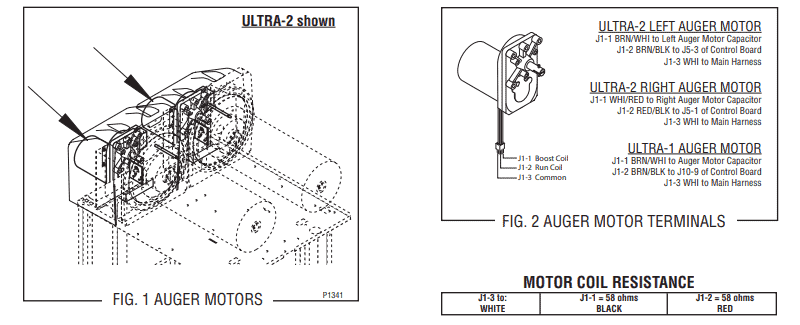
- Step 1. Unfasten both #8 locking screws that secure the auger motor cover to the cooling drum mount assembly. Remove the cover.
- Step 2. Remove the #8 locking screw on the lower right side of the auger motor mounting bracket that holds the auger motor run capacitor.
- Step 3. Disconnect the auger motor terminal from the main wiring harness terminal.
- Step 4. Unfasten the three remaining #8 locking screws that secure the auger motor cover to the cooling drum mounting bracket.
- Step 5. Remove the motor. Make sure to remove it as an assembly with the mounting bracket, drip tray, split pin and torsion spring bearing. Whenever you remove or install the motor, the split pin in the motor shaft should be turned to a position what clears the torsion sensor circuit board.
- Step 6. Install the new motor. This should be an assembly that includes a mounting bracket, drip tray, split pin and torsion spring bearing. Use three #8 locking screws to secure the mounting bracket to the cooling drum bracket.
- Step 7. Using the remaining #8 locking screws, attach the auger motor capacitor on the lower right side of the auger motor mounting bracket.
- Step 8. Connect the auger motor terminal to the terminal on the main wiring harness. Refer to FIG. 2 above for reconnecting wires.
Replacing an Auger Motor Capacitor
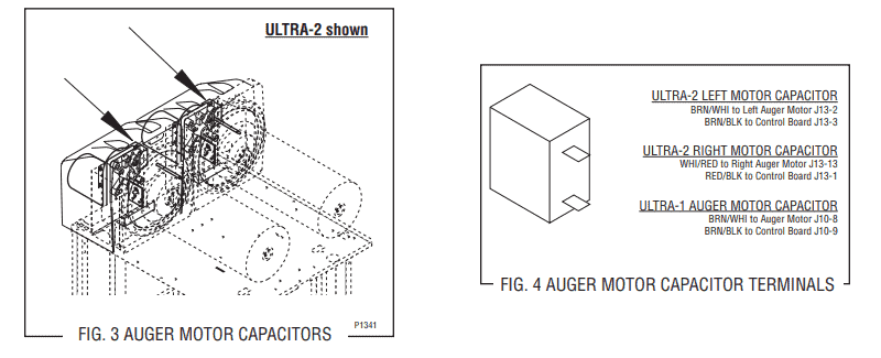
The auger motor capacitor in an ULTRA-1 and ULTRA-2 slush machine is at the lower right side of the auger motor mounting bracket inside the motor cover. Remove and replace the auger motor using the following procedures:
- Step 1. Unfasten both #8 locking screws that secure the auger motor cover to the cooling drum mount assembly. Remove the cover.
- Step 2. Disconnect the wiring from the auger motor capacitor terminals.
- Step 3. Remove the #8 locking screw on the lower right side of the auger motor mounting bracket that secure the auger motor capacitor.
- Step 4. Attach the new capacitor to the lower right side of the auger mounting bracket. Secure it using a #8 locking screw.
- Step 5. Reconnect the wiring to the capacitor terminals. Refer to FIG. 4 above for reconnecting wires.
Replacing an Auger Shaft Assembly
The auger shaft assembly in an ULTRA-1 and ULTRA-2 slush machine is in the cooling drum. Remove and replace the auger shaft assembly using the following procedures:
- Step 1. Drain and clean the hopper following the cleaning instructions outlined in your operator's manual. Dispose the hopper/drum seal and faucet seal.
- Step 2. Unfasten the #8 locking screws that secure the motor cover to the cooling drum mount assembly. Remove the cover.
- Step 3. Remove the #8 locking screw on the lower right side of the auger motor mounting bracket that secures the auger motor run capacitor. Make sure to set aside the capacitor with the wiring still attached.
- Step 4. Disconnect the auger motor terminal from the main wiring harness terminal.
- Step 5. Unfasten the remaining #8 locking screws that secure the auger motor mounting bracket to the cooling drum mounting bracket.
- Step 6. Remove the motor assembly, which includes the motor, mounting bracket, drip tray, split pin and torsion spring bearing. Whenever you remove or install the motor, the split pin in the motor shaft should be turned to a position what clears the torsion sensor circuit board.
- Step 7. Pull the auger shaft assembly out of the cooling drum. Check the shaft for abnormal wear or scoring.
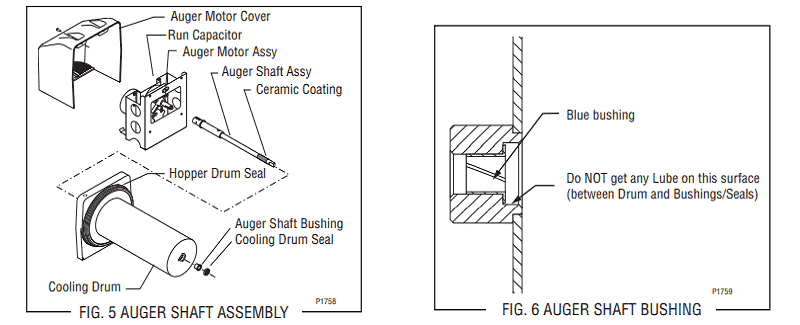
- Step 8. From the dispenser's front, remove the seal and blue bushing from the cooling drum. Discard them.
- Step 9. Clean the seal and bushing surfaces of the cooling drum thoroughly. Slip the new blue bushing into the cooling drum. Refer to FIG. 6 above for guidance.
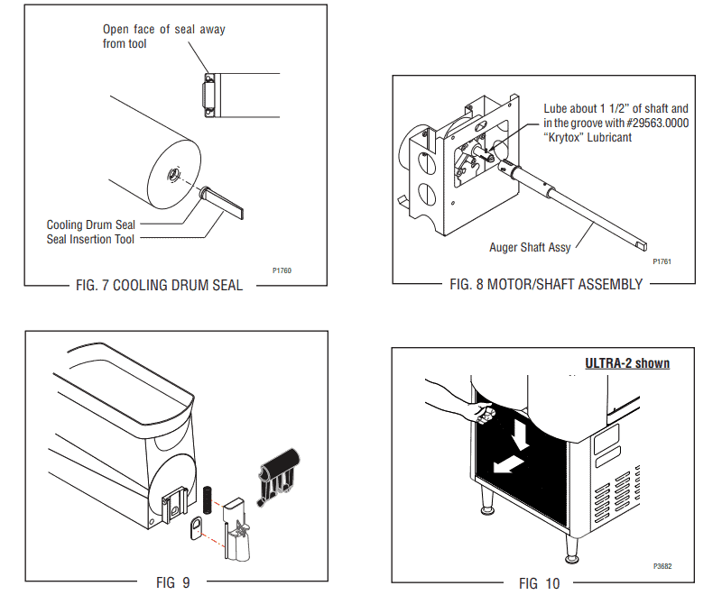
- Step 10. Place the seal on the insertion tool (No. 28395.0000). Refer FIG. 7 above. Ensure that the open face of seal is toward cooling drum. Then, push the seal into the bore until it's firmly seated. Remove the tool.
- Step 11. Place a little bit of Krytox lubricant (No. 29563.0000) on the end of the motor shaft (about 1.5″) and a thin film in the groove. Install the auger shaft assembly onto the motor shaft. Refer to FIG. 8 for guidance.
- Step 12. Assemble the motor and shaft assembly as referenced in FIG. 8. Then, install the assembly into the cooling drum. Make sure the pins don't hit the sensor board and that the cooling drum seal isn't dislodged as the shaft passes through.
- Step 13. Secure the motor and capacitor to the cooling drum mounting bracket. Place the rear motor cover back on.
- Step 14. Install the hopper assembly by referring to the “Hopper Installation” in the manual referenced below. Use new hopper/drum seal and faucet seals.
- Step 15. Remove and clean the condenser air filter seen in FIG 10 above.
- Step 16. Go to the “Menu Function Index.” Scroll to menu “PM Complete?” and answer “YES.” This will reset the reminder message “PM Due.”
Replacing the Control Board
The control board on an ULTRA-1 and ULTRA-2 slush machine is behind the front panel on the front chassis. Remove and replace the control board if voltage is present as described and the dispenser doesn't operate. Use the following procedures:
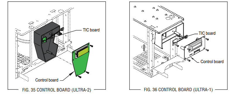
- Step 1. Disconnect the main harness from connector on the control board. This will be J5 on an ULTRA-2 or J9 on an ULTRA-1.
- Step 2. Remove the four #8-18 pan head screws that secure the control board to the mounting box. Disconnect TIC memory board from connector J1 on the control board. On models with Auto-Fill, make sure to also remove the auto-fill adapter board.
- Step 3. When you install the new control board, start by reconnecting the TIC board to connector J1.
- Step 4. Secure the control board to the mounting box using the four #8-18 pan head screws.
- Step 5. Reconnect the main harness to J5 on an ULTRA-2 or J9 on an ULTRA-1 on the control board.
Please refer to FIG. 35 and FIG. 36 above for guidance.
Replacing the Fan on ULTRA-1 Model
The fan on an ULTRA-1 slush machine is inside the rear of the dispenser chassis behind the condenser. Remove and replace the fan using the following procedures:
- Step 1. Disconnect the dispenser from the power source.
- Step 2. Remove the air filter from the back of the dispenser.
- Step 3. Remove the four #8-32 hex screws attaching the fan and shroud assembly to the condenser frame.
- Step 4. Detach the wiring harness from the fan that is being replaced.
- Step 5. Remove the four screws that attaches the fan to the fan shroud. You can now replace the fan.
- Step 6. When installing the new fan, ensure it's directed in a way where the airflow matches that of the remaining fan. The arrow on the fan should point toward condenser.
- Step 7. Reconnect the fan to the main wiring harness. Then, install the fan and shroud assembly to the condenser frame.
- Step 8. Replace the air filter and reconnect the dispenser to the power source.
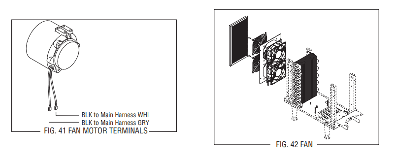
Replacing the Fan on ULTRA-2 Model
The fan on an ULTRA-2 slush machine is inside the dispenser chassis in the front of the condenser. Remove and replace the fan using the following procedures (reference FIG. 40 above):
- Step 1. Leave the hopper in place, so it's aligned while the condenser shroud is removed. Start by disconnecting the fan leads from the wiring harness.
- Step 2. Remove the four #6 crimptite screws that secure the condenser shroud and the fan assembly to the condenser. Also, remove the two #8-32 locking screws that secure the condenser shroud and the fan assembly (1) to the chassis base. Once all the screws are unfastened, remove the condenser shroud and fan assembly (1) from the right side of the dispenser.
- Step 3. Remove the three #6 thread cutting screws securing the fan assembly to the condenser shroud (7). Set aside the condenser shroud and screws for reassembly.
- Step 4. Remove the three #8-32 thread forming screws securing motor (5) to the condenser fan shroud/mount (6). Set aside the shroud and screws for reassembly.
- Step 5. Remove the speed nut (2) from the motor shaft. Then, remove the fan (3).
- Step 6. Remove the silencer (4): Condenser shroud and fan assembly, speed nut, fan blade, silencer, motor, shroud/mount and condenser shroud.
- Step 7. Install the silencer (4) on the new motor assembly. Then, install the fan (3) on the new motor assembly, speed nut on the new motor assembly.
- Step 8. With the three #8-32 thread forming screws, secure the new motor assembly to the shroud/mount (6).
- Step 9. With the three #6-32 thread cutting screws, secure the new motor and the shroud/mount to the condenser shroud (7).
- Step 10. With the two #8-32 locking screws, secure the condenser shroud and the fan assembly (1) to the chassis base.
- Step 11. With the four #8-32 crimptite screws, secure the condenser shroud and the fan assembly (1) to the condenser.
- Step 12. Reconnect the leads on the new motor to the dispenser wiring harness. Refer to FIG. 41 above for guidance.
- Step 13. Use cable ties to secure the wiring away from the fan blades.
More Bunn Slush Machine Repairs
Below are other repairs authorized technicians might need to explore over time. Click on the link belownfor instructions and refer to the table of contents:
Check out the full Bunn ULTRA Slush Machine service and repair manual.
Repair Table of Contents
- Access Panels – page 22
- Circuit Breaker – page 27
- Compressor – pages 28, 31, 38, 41
- Relay – page 43
- Cooling Drum Alignment – page 45
- Fan – pages 46, 47
- Hot Gas Sensor – page 48
- Lamp Cord Assembly – page 49
- Lamp Cord Connector – page 50
- Lamp Holder/Socket Assembly – page 51
- LED Lamps – page 52
- Lamp Relay – page 53
- Membrane Switch – page 54 ,55
- Solenoids – page 56
- Temperature Sensor Assembly – page 57
- Torque Sensor Circuit Board – page 58
- Transformer – page 59
- Auto Fill Systems – page 60, 62