
-
Tips of the Trade
-
Tools & Gear
- How to Use a Plumbing Snake
- What is True RMS
- 8 Best HVAC PPE for the Job
- 4 Ways to do Cordless Tool Storage in a Service Truck
- Best Power Saws for Technicians
- Learn How to Test a Fuse with a Multimeter in 5 Steps
- Best HVAC Service Wrenches
- Best Wire Crimper Tools in 2023
- Best Automatic Wire Strippers for Technicians in 2023
- Types of HVAC Safety Glasses
- 7 Types of Electrical Testers & Their Uses
- Best Multi Tool Kits for 2023
- 5 Best Wire Strippers for Technicians for 2023
- Best HVAC Hand Tools for 2023
- 7 Best Electrician Pliers for Technicians in 2023
- Best Oscillating Tools for Technicians in 2023
- Best Flashlights for Technicians in 2023
- Best Power Tools for Electricians in 2023
- A Fast & Easy Guide on How to Calibrate a Multimeter
- Master How to Use Wire Strippers in 7 Steps or Less
- Discover How to Find a Ground Wire in 4 Different Ways
- Air Tools vs. Electric Tools: Discover 5 Pros & Cons
- Best Thermal Imaging Cameras for HVAC
- How to Measure Current with a Multimeter in 5 Steps
- 4 Best Power Tool Batteries of 2023
- Which Cordless Drill is Best for HVAC Work?
- 4 Top Cordless Impact Drivers of 2023
- How to Test a Wire for Voltage in 5 Steps
- Voltage Tester vs. Multimeter: What's the Difference?
- Fluke Vs. Klein Multimeters: Which One Better Meets Your Needs
- 4 Best Multimeters for HVAC in 2022 & 2023
- Best Cordless Power Tools for 2022 & 2023
- Show all articles ( 17 ) Collapse Articles
-
HVAC
-
Food Prep
-
Dishwashing & Warewashing
-
Beverage
-
Cold Side
-
- Ice-O-Matic CIM Error Light Diagnostics
- Ice-O-Matic CIM Pump Replacement Instructions
- Ice-O-Matic GEMU090 Pump Kit Installation Instructions
- Hoshizaki Water Filter System Installation
- Hoshizaki Ice Machine Repair & Replacement Guides For Technicians
- Danfoss Controller Reset
- Scotsman Ice Machine Repair
- How to Install a Hoshizaki Ice Machine
- How to Install a Scotsman Ice Machine
- Resolving Manitowoc Ice Maker T3 and T4 error codes
- Changing a Manitowoc Ice Machine Water Pump
- Ice-o-Matic Troubleshooting Starts with a Reset
- Strategies to Find Leaks That Pool in Ice Bins
- How to Resolve the E24-T4 Error Code on Manitowoc Ice Makers
- Manitowoc Control Board Replacement
- Manitowoc Ice Machine Installation for Authorized Technicians
- Ice-O-Matic Timer Adjustment
- Manitowoc Ice Training Resources for Technicians
- Show all articles ( 3 ) Collapse Articles
-
- Refrigeration Capillary Tube Troubleshooting for Technicians
- Danfoss Controller Reset
- How to Recharge the Freon in a Commercial Refrigerator or Freezer
- Dixell Controller Factory Reset Instructions
- How to Replace a Temperature Controller on a True Freezer Model t-49f
- How to Tell Whether Your TXV is Bad
- How to Remagnetize a Refrigerator/Freezer Door Seal
- R32 vs R290 vs R134a vs R12 Refrigerant
- How to Resolve the “HA” Error Code on Perlick Bar Coolers
- U.S. Refrigerant Phase Out Chart & Info
- Global Warming Potential of Refrigerants
- True Traditional Reach-In & GDM Wire Gauge Charts for Authorized Technicians
- Nor-Lake Capsule Pak Walk-In Cooler Installation
- What Happens If You Put R134a in an R12 System?
- How to Remove Continental Refrigerator Electrical Controls for Authorized Technicians
- Continental Refrigerator Error Codes & Resolutions for Authorized Technicians
- R134a Pressure Chart for Refrigerators, Prep Tables & More
- How to Adjust a Kolpak Walk-In Door Sweep
- Replacing a Kolpak Walk-In Freezer Door Heater Wire
- Adjusting Kolpak Walk-In Cooler Door Hinges & Closers
- Replacing a Kolpak Walk-In Door Gasket & Handle
- Kolpak Walk-In Cooler Installation
- What Pressure Should R404a Run at on a Cooler?
- What is R134a Replacement?
- How to Conduct Diagnostics on Delfield Specification Line
- How to Replace a Delfield Specification Line Touchscreen
- How to Change Danfoss ERC Controllers
- R12 to R134a Conversion Chart & Formula
- Show all articles ( 13 ) Collapse Articles
- Ice-O-Matic CIM Error Light Diagnostics
- Ice-O-Matic CIM Pump Replacement Instructions
- Ice-O-Matic GEMU090 Pump Kit Installation Instructions
- Refrigeration Capillary Tube Troubleshooting for Technicians
- When and How to Adjust a Thermostatic Expansion Valve (TXV)
- Hoshizaki Ice Machine Repair & Replacement Guides For Technicians
- Danfoss Controller Reset
- Scotsman Ice Machine Repair
- How to Recharge the Freon in a Commercial Refrigerator or Freezer
- Dixell Controller Factory Reset Instructions
- How to Replace a Temperature Controller on a True Freezer Model t-49f
- How to Install a Hoshizaki Ice Machine
- How to Install a Scotsman Ice Machine
- Resolving Manitowoc Ice Maker T3 and T4 error codes
- Changing a Manitowoc Ice Machine Water Pump
- Ice-o-Matic Troubleshooting Starts with a Reset
- How to Tell Whether Your TXV is Bad
- How to Remagnetize a Refrigerator/Freezer Door Seal
- R32 vs R290 vs R134a vs R12 Refrigerant
- How to Resolve the “HA” Error Code on Perlick Bar Coolers
- U.S. Refrigerant Phase Out Chart & Info
- Strategies to Find Leaks That Pool in Ice Bins
- Global Warming Potential of Refrigerants
- How to Resolve the E24-T4 Error Code on Manitowoc Ice Makers
- True Traditional Reach-In & GDM Wire Gauge Charts for Authorized Technicians
- What is R22 Refrigerant?: Phase Out, Alternatives & More
- Nor-Lake Capsule Pak Walk-In Cooler Installation
- What Happens If You Put R134a in an R12 System?
- Manitowoc Control Board Replacement
- How to Remove Continental Refrigerator Electrical Controls for Authorized Technicians
- Continental Refrigerator Error Codes & Resolutions for Authorized Technicians
- R134a Pressure Chart for Refrigerators, Prep Tables & More
- Manitowoc Ice Machine Installation for Authorized Technicians
- Ice-O-Matic Timer Adjustment
- How to Adjust a Kolpak Walk-In Door Sweep
- Replacing a Kolpak Walk-In Freezer Door Heater Wire
- Adjusting Kolpak Walk-In Cooler Door Hinges & Closers
- Replacing a Kolpak Walk-In Door Gasket & Handle
- Kolpak Walk-In Cooler Installation
- What Pressure Should R404a Run at on a Cooler?
- What is R134a Replacement?
- Manitowoc Ice Training Resources for Technicians
- How to Conduct Diagnostics on Delfield Specification Line
- How to Replace a Delfield Specification Line Touchscreen
- How to Change Danfoss ERC Controllers
- R12 to R134a Conversion Chart & Formula
- Show all articles ( 31 ) Collapse Articles
-
-
Equipment Shutdown Procedures
- Garland Grill Shutdown and Startup Procedure
- Convotherm Mini Combi Shutdown and Startup Procedures
- Manitowoc Ice Machine Shutdown and Startup Procedures
- Long Term Shutdown of Randell Preparation Tables and Freezers
- Nieco Broiler Long Term Shutdown and Startup Procedures
- Blodgett Convection Oven Long Term Shutdown
- Blodgett Combi Oven Long Term Shutdown Procedure
- APW Wyott, Bakers Pride & Star Brands Equipment Shutdown Procedures
- Pitco Fryer Shutdown Procedure
- Ultrafryer Shutdown procedure
- ANETS Fryer Shutdown Procedure
- Henny Penny McDonalds LOV Fryer Long Term Shutdown
- Henny Penny Long Term Fryer Shutdown
- ShutDown procedure for AccuTemp Evolution Steamer
- AccuTemp Accu-Steam Griddle shutdown procedure
-
Hot Side
-
- PST/PGT/PSC Star Sandwich Grill Troubleshooting for Technicians
- How to Run PGT/PCS/PSC/PST Star Sandwich Grill Diagnostics
- Removing & Replacing a Garland SIT Thermocouple
- Garland SIT Knob Alignment & Calibration
- Checking a Garland SIT Control Safety Valve
- Garland SIT Control Adjustment & Replacement
-
- Deep Fryer Hi Limit Replacement Instructions
- How to Diagnose a Deep Fryer Thermostat
- Deep Fryer Thermostat Calibration Instructions
- Deep Fryer Thermostat Replacement Instructions
- How to Set a Garland Fryer Temperature
- Dormont Installation Guide for Technicians
- How to Test and Replace the Gas Safety Valve on a Pitco Fryer
- How To Light Commercial Gas Appliances
- How To Convert Appliances From Natural Gas To Propane
- Frymaster Tech Training - Troubleshooting a Fryer with an MIB
- Frymaster Tech Training - MIB Operation on an Automatic Filter Fryer
-
- Removing the UI Board from an Ovention Matchbox 1718: Tech Tips
- Removing the SD Card from an Ovention Matchbox 1718: Tech Tips
- Removing the LCD Screen from an Ovention Matchbox 1718: Tech Tips
- Resetting the High Limit on an Ovention Matchbox 1718: Tech Tips
- How to Light a Commercial Gas Oven?
- Dormont Installation Guide for Technicians
- How To Adjust Commercial Oven Door Hinges?
- How To Light Commercial Gas Appliances
- How To Convert Appliances From Natural Gas To Propane
- Blodgett Combi Error Codes for Authorized Technicians
- Blodgett Oven Door Adjustment
- Lincoln Pizza Oven Repair & Installation for Authorized Technicians
- Lincoln Impinger Pizza Oven Parts Diagram
- Changing the Direction of the Conveyor on a Star Ultra Max Conveyor Oven
- Water Column to PSI Conversion Chart & Formula
- Removing & Replacing a Garland SIT Thermocouple
- Garland SIT Knob Alignment & Calibration
- Checking a Garland SIT Control Safety Valve
- Garland SIT Control Adjustment & Replacement
- Show all articles ( 4 ) Collapse Articles
- Deep Fryer Hi Limit Replacement Instructions
- How to Diagnose a Deep Fryer Thermostat
- Deep Fryer Thermostat Calibration Instructions
- Deep Fryer Thermostat Replacement Instructions
- How to Set a Garland Fryer Temperature
- Removing the UI Board from an Ovention Matchbox 1718: Tech Tips
- Removing the SD Card from an Ovention Matchbox 1718: Tech Tips
- Removing the LCD Screen from an Ovention Matchbox 1718: Tech Tips
- Resetting the High Limit on an Ovention Matchbox 1718: Tech Tips
- How to Light a Commercial Gas Oven?
- How to Check Inlet Gas Pressure
- Dormont Installation Guide for Technicians
- How To Adjust Commercial Oven Door Hinges?
- How to Test and Replace the Gas Safety Valve on a Pitco Fryer
- How To Light Commercial Gas Appliances
- How To Convert Appliances From Natural Gas To Propane
- Blodgett Combi Error Codes for Authorized Technicians
- Blodgett Oven Door Adjustment
- Lincoln Pizza Oven Repair & Installation for Authorized Technicians
- Lincoln Impinger Pizza Oven Parts Diagram
- PST/PGT/PSC Star Sandwich Grill Troubleshooting for Technicians
- How to Run PGT/PCS/PSC/PST Star Sandwich Grill Diagnostics
- Changing the Direction of the Conveyor on a Star Ultra Max Conveyor Oven
- Water Column to PSI Conversion Chart & Formula
- Removing & Replacing a Garland SIT Thermocouple
- Garland SIT Knob Alignment & Calibration
- Checking a Garland SIT Control Safety Valve
- Garland SIT Control Adjustment & Replacement
- Frymaster Tech Training - Troubleshooting a Fryer with an MIB
- Frymaster Tech Training - MIB Operation on an Automatic Filter Fryer
- Frymaster Series 35 Troubleshooting guide
- Show all articles ( 16 ) Collapse Articles
-
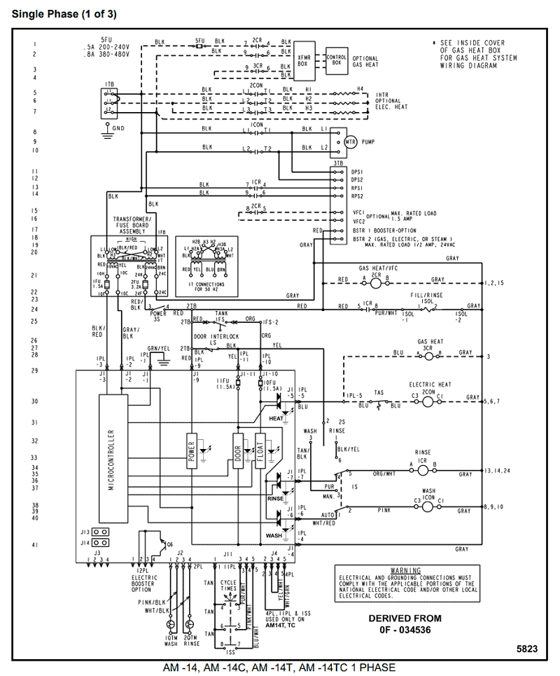
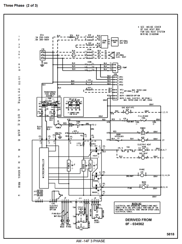
Hobart AM 14 Wiring Diagrams for Authorized Technicians
Hobart AM 14 Series Dishwashers are used in a wide variety of commercial kitchens. When service technicians are called to make repairs inside the unit, having the right resources are crucial. Wiring diagrams can be a tech's best friend. These drawing show electrical systems or circuits in a machine, including where components and terminals appear and how they connect. This makes it easier to tackle any repair, installation or detailed troubleshooting. If you don't have them readily available, below are Hobart AM 14 wiring diagrams to use for reference.
NOTE: These diagrams are only for authorized Hobart technicians. Equipment operators should contact a local Hobart service agent to conduct the tasks outlined below as well as additional repairs.
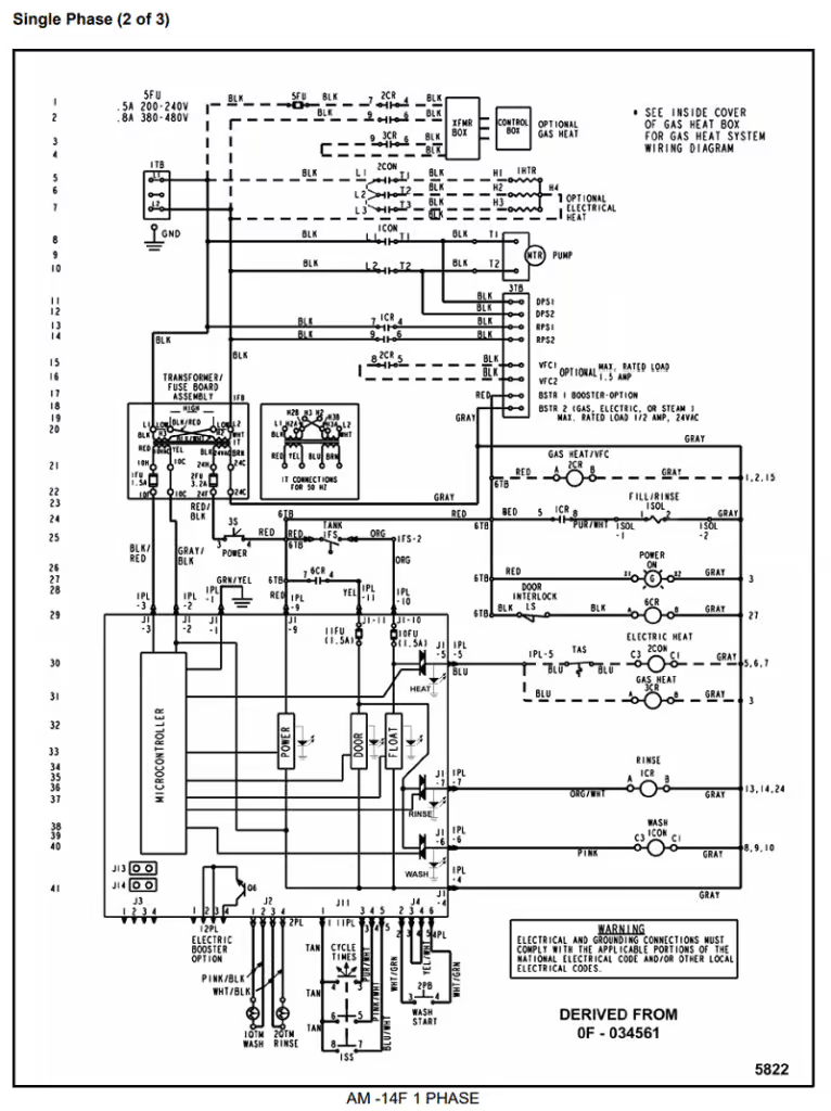
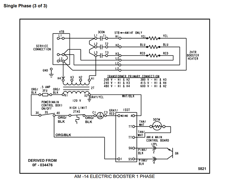
1 Phase Diagrams
The following 1 phase wiring diagrams are for the Hobart 14 AM series dishwashers:
AM 14, AM 14C, AM 14T, AM 14TC
AM 14F
AM 14 Electric Booster
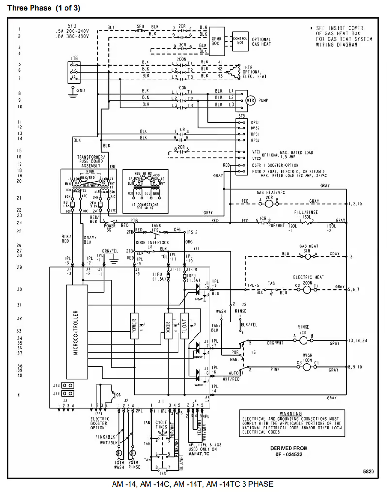
3 Phase Diagrams
The following 3 phase wiring diagrams are for the Hobart 14 AM series dishwashers:
AM 14, AM 14C, AM 14T, AM 14TC
AM 14F
AM 14 Electric Booster
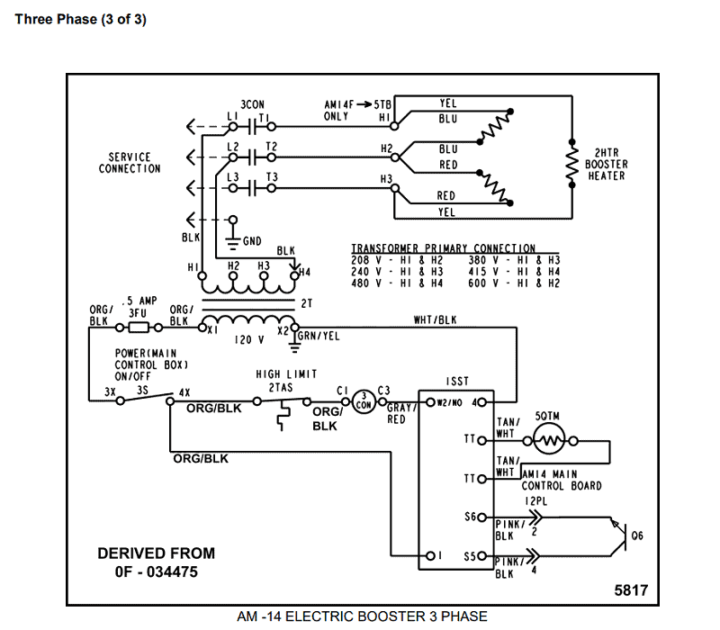
*Source: SERVICE MANUAL SUPPLEMENT AM 14 SERIES and 13 kW ELECTRIC BOOSTER OPTION (pages 21-26)